Transtibial Prosthetic Design
Spring-assisted lower-limb prosthetic concept designed to generate an assistive ankle moment during walking.
Overview
Collaborated on the design of a spring-assisted transtibial prosthetic intended to generate an assistive ankle moment during walking. The concept uses two extension springs, a motor-driven ball screw, and a translating plate to support plantarflexion during gait. My primary contributions included selecting commercially available mechanical components, developing and integrating the SolidWorks assembly, and supporting the overall system design. The team also performed mechanical and power analyses and developed an estimated component cost of approximately $2,184.95.
Project Details
Duration
10 weeks
Role
Mechanical Design Engineer
Four biomedical engineering students
Team
Project Type
Conceptual Design and Analytical Validation
SolidWorks
MATLAB
Microsoft Excel
Microsoft Word
Software
Mechanical Design
CAD Modeling
Spring Selection
Component Selection
Anthropometric Design
Biomechanics
Skills
Individuals with transtibial amputations may experience reduced ankle power and altered gait because a conventional prosthetic does not fully reproduce the dorsiflexion and plantarflexion generated by the biological ankle. The challenge was to develop a lower-limb prosthetic concept capable of producing an assistive ankle moment while remaining mechanically feasible, dimensionally appropriate, and economical. The design also needed to accommodate a motor, transmission system, springs, socket, and structural components within the limited space of a lower-leg prosthesis.
The Challenge
Design Objectives
Generate an assistive ankle moment during gait
Use spring energy to reduce motor demand
Translate motor rotation into controlled linear motion
Prevent unwanted rotation of the spring plate
Fit dimensions derived from anthropometric data
Use commercially available components where possible
Maintain adequate mechanical factors of safety
Keep the estimated cost below typical advanced prosthetic systems
Human-Centered Design Basis
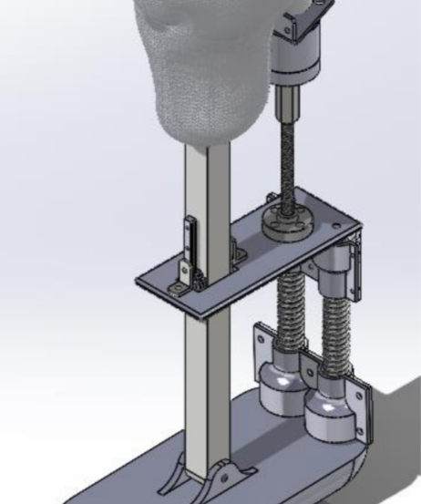
The concept was developed for a representative user measuring 5 ft 10 in and 80 kg. Lower-leg and foot dimensions were selected from anthropometric datasets to guide the overall prosthetic length, socket position, and approximate foot geometry. The socket concept used a carbon-fiber shell with a soft, 3D-printed TPU or TPE liner to support fit and comfort.
System Concept
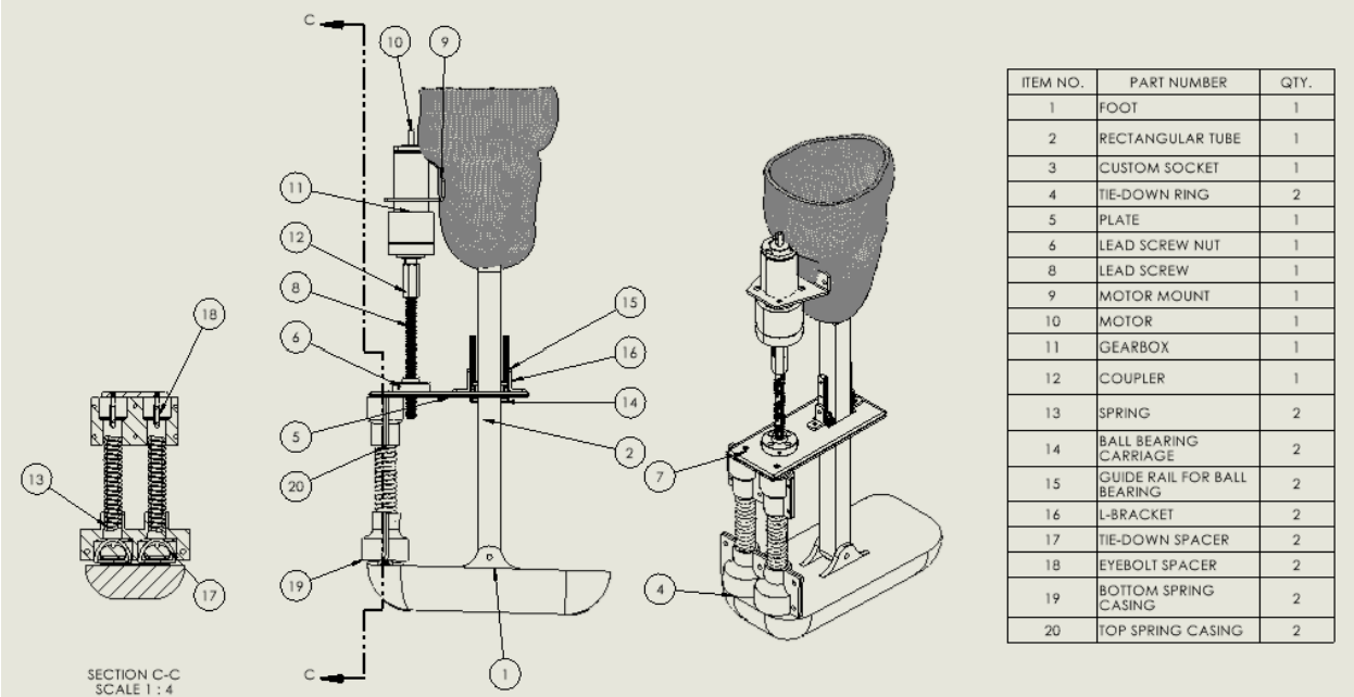
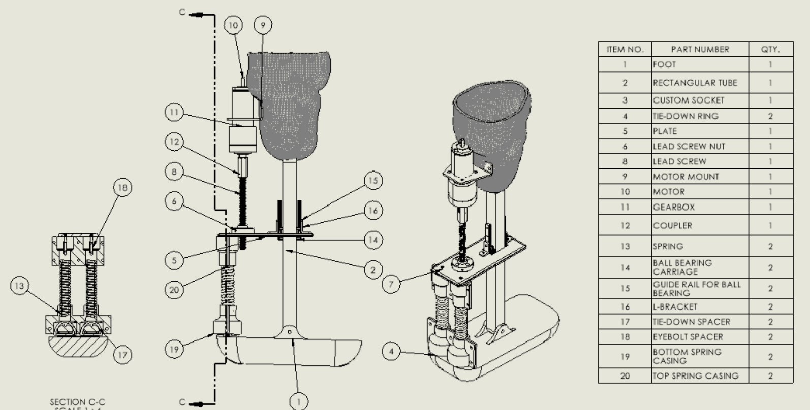
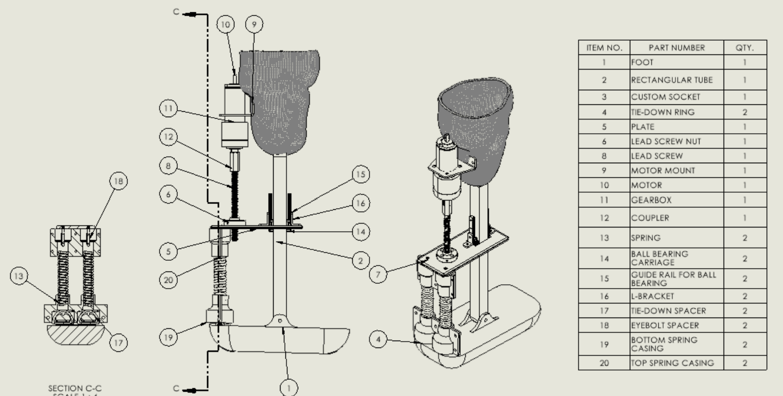
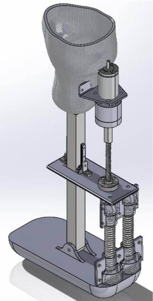
The proposed system uses two extension springs positioned behind the heel to assist ankle plantarflexion. A motor and gearbox rotate a ball screw, causing a flange nut and attached aluminum plate to translate vertically. The plate tensions the springs, which then apply force to the heel and create a moment about the ankle joint. A square aluminum shaft guides the translating plate and prevents unwanted rotation, while linear bearing carriages support vertical movement.
Main Components
Dual Extension Springs
Store and release mechanical energy to assist ankle motion.
Motor and Gearbox
Provide the rotary input required to adjust spring tension.
Ball Screw and Flange Nut
Convert rotary motor motion into controlled linear translation.
Spring Plate
Connects the ball screw assembly to the two springs.
Square Guide Shaft
Prevents the translating plate from rotating.
Linear Bearing Carriages
Guide the spring plate vertically.
Socket and Prosthetic Foot
Connect the system to the user and transfer load to the ground.
Engineering Analysis
Spring Design
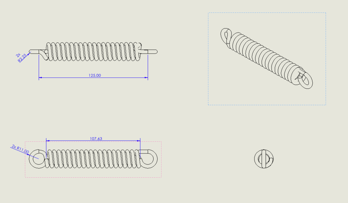
Gait data and ankle-moment calculations were used to determine the spring stiffness required to reduce motor power during walking. MATLAB simulations evaluated multiple spring configurations and identified an optimal system stiffness of approximately 34,324 N/m. Because a single commercially available spring could not meet the required performance within the available geometry, two extension springs were selected in parallel to achieve the desired stiffness while maintaining acceptable safety factors.
Motor Selection
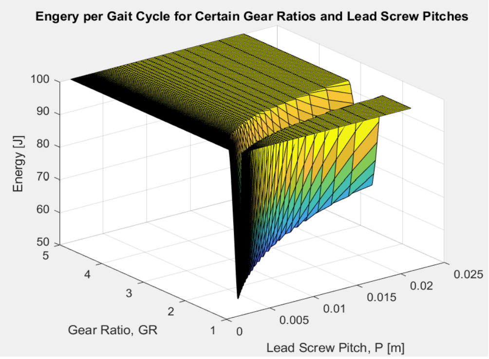
A MATLAB model evaluated motor efficiency across a range of torque and speed operating conditions to estimate system power requirements. The analysis predicted a peak mechanical power demand of approximately 166.5 W, leading to the selection of a Maxon EC40 motor rated at 170 W. A 15.2 V, 9000 mAh battery was selected to satisfy the anticipated daily energy requirements while maintaining a compact system footprint.
Ball Screw and Structural Analysis
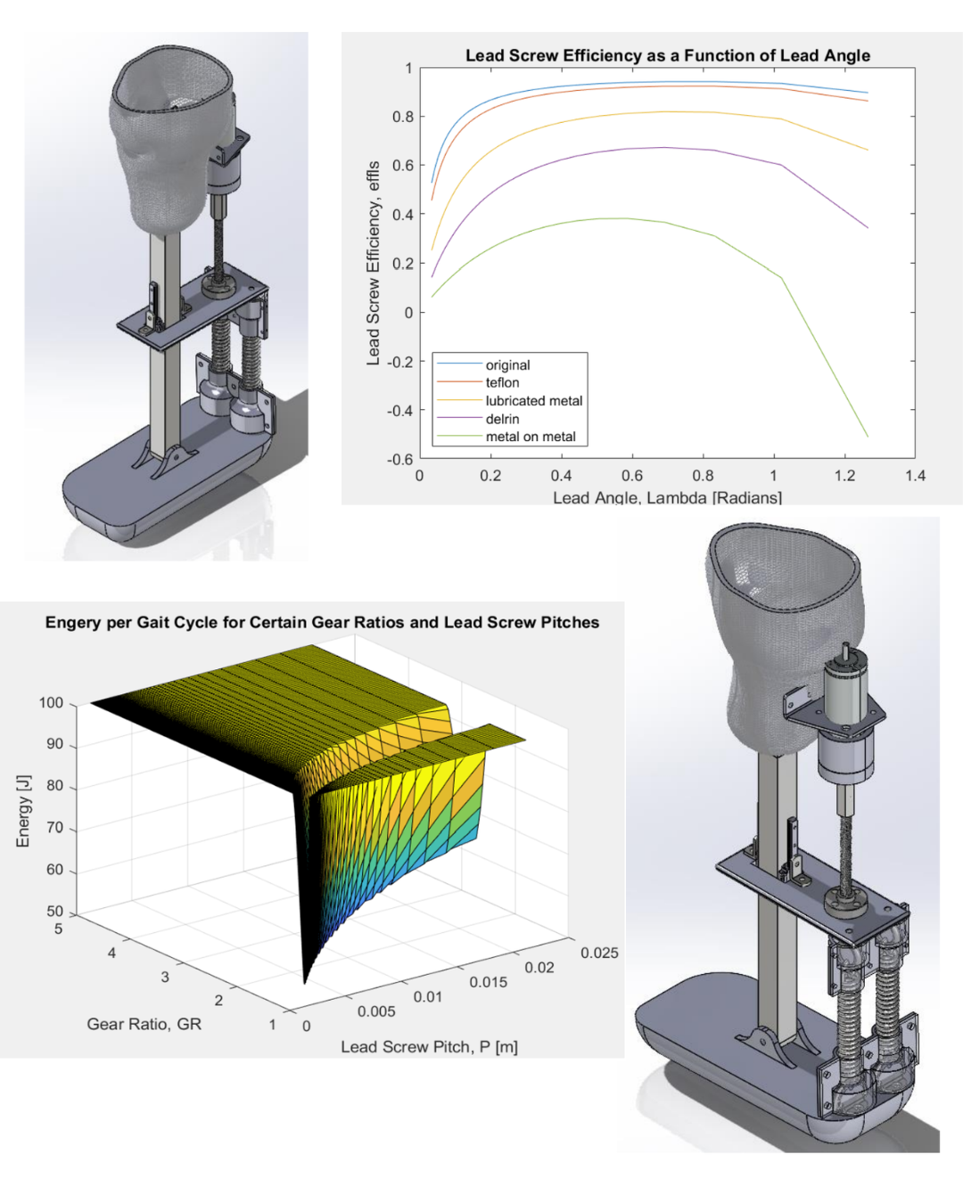
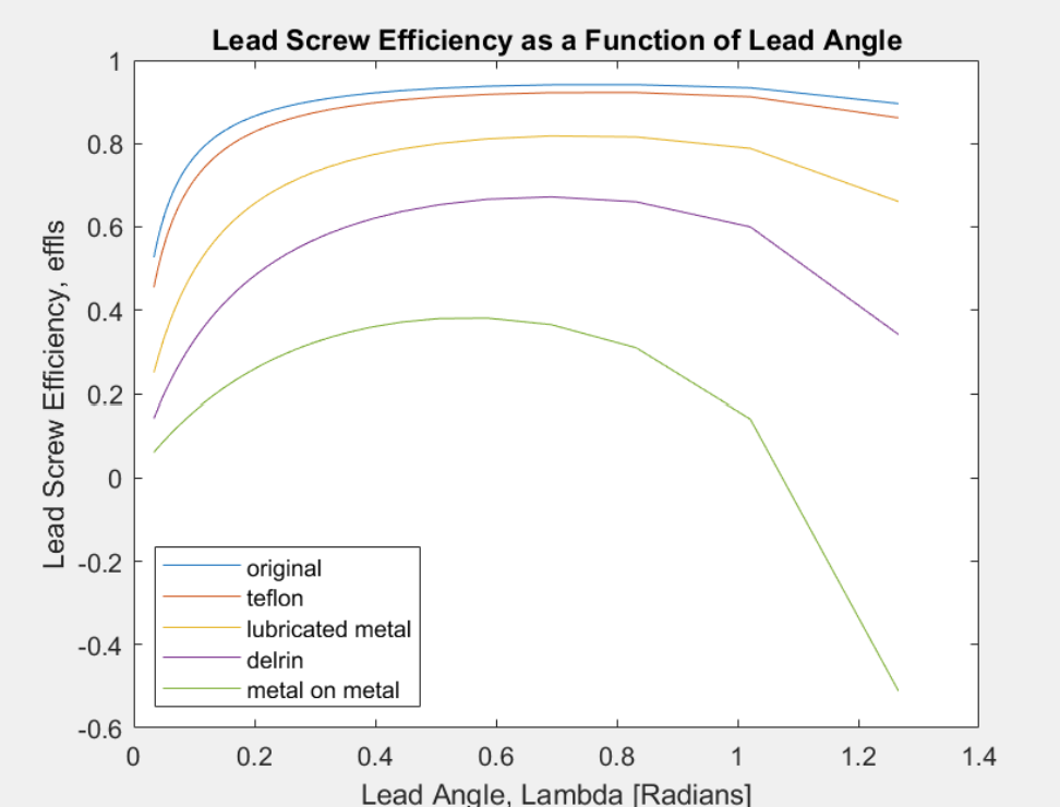
The drivetrain was designed around an M10 × 2 ball screw, selected over a conventional lead screw to improve efficiency and reduce friction. Analytical calculations and MATLAB models were used to evaluate gear ratio, screw efficiency, bending stress, buckling, shear, and bearing loading. The selected configuration achieved an estimated 86.5% transmission efficiency while meeting the required mechanical safety factors for the ball screw, guide shaft, and bearing carriage assembly.
Mechanical Design
The final CAD concept integrates the socket, motor, gearbox, ball screw, translating plate, dual springs, square guide shaft, bearing carriages, ankle hinge, and prosthetic foot into a single assembly. The springs operate in tension and attach between the translating plate and heel. As the ball screw moves the plate vertically, the springs are tensioned to generate an assistive ankle moment. The square shaft constrains the plate against rotation, while the bearing carriages maintain linear motion.
Component Selection and Cost
A complete bill of materials was developed using commercially available components and custom-fabricated parts. The estimated system cost was $2,184.95, including the socket, motor, gearbox, encoder, battery, ball screw, springs, linear guides, structural components, and 3D-printed parts. The cost estimate demonstrated that the proposed concept could potentially be developed at a substantially lower component cost than many advanced powered prosthetic systems, although manufacturing, clinical fitting, testing, and regulatory costs were outside the scope of the estimate.
Design Outcomes
The project produced a complete CAD-based prosthetic concept supported by gait analysis, spring optimization, motor modeling, ball-screw calculations, component selection, and structural safety checks. The design met the team’s objective of creating a mechanically feasible system capable of generating an assistive ankle moment through a combination of powered linear motion and spring tension. The analysis also identified areas requiring further development, particularly the socket, prosthetic foot, custom screw geometry, system weight, and user testing.
Reflection
This project highlighted how closely interconnected every subsystem of a prosthetic device is. A change to the spring stiffness affected motor power, ball-screw selection, component dimensions, and the overall package. The project taught me to evaluate mechanical components as part of a complete system rather than as isolated parts. It also reinforced the importance of clearly distinguishing between an analytically feasible concept and a design that has been physically and clinically validated.